So let’s rewind 7 months ago, when I was still in senior year of college. One of my final projects I was working on for my club was a drink dispensing robot. We were close to finishing the robot, but I could not get the motor drive working for it. No matter how much I tried, the circuitry for the motor controller kept burning out. I felt so ashamed because I could not figure out what was wrong with the circuit. Fast forward to today and I wanted to try to correct the mistakes I made for that project by working on a similar one. So, one of my new projects is a 24V brushed motor controller using Arduino.
So, I want the final version to be implemented as an Arduino Uno shield. The shield will allow the user to control two 24V DC motors and limit the current 10 amps (5 amps per motor). If one of the motors draw more than 5 amps, then the shield will shut off power to both motors. The shield should also provide some level of isolation between the Arduino and the motor controller. By providing some isolation between the Arduino and the motor controller, the Arduino will not get damaged during overcurrent condition. To control the direction of both motors, I will be making a homebuilt Hbridge using a combination of pchannel and nchannel mosfets. For my pchannels mosfets, I used Fairchild’s FQP27P06. As for nchannel mosfets, I used FQP20N06.
Normally, I would talk about the theory behind the brushed motor controller shield and talk about testing later, but I drew a lot of the schematics by hand and will need to be either re-scanned or converted to an Eagle Cad schematic. I will mention that for driving the pchannels and nchannels, I used IR’s IR4427 dual low side gate driver.
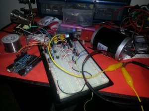
Arduino motor controller implemented on a breadboard
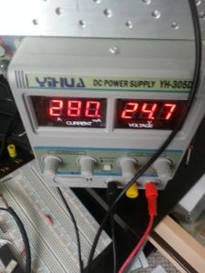
The figure above shows my first implementation of the motor control circuit. This motor control circuit should allow me to change the direction the motor is rotating. For testing the circuit, I used a 24V scooter motor I brought from Ebay. Despite the fact the motor is a 120W motor, the motor will not be loaded. By not loading the motor, the motor draws a couple of milli-amps (200-300ma) when I connected 24V to it using my 32V/5A DC power supply. Because of this, I thought it would be unnecessary to heatsink some of the parts of the circuit.After building the circuit, I was able to safely power the motor from 12V-19V, but then one of the motor control transistors burned out. “Why?” you ask? Because by the time I put 18V into the circuit/motor, it was drawing 2.5A.
One of the pchannel mosfets was damaged around 18V.
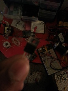
How could this be? If I provided a heatsink to each of the transistors as I should of, I could of pump 24V into the motor easily. To fix this situation, I was going to have to either grab a couple of heatsinks, or grab a piece of metal to act like a giant heatsink and attach the transistors to the piece of metal with sol-pads on the back. I also going to need to buy some more p channel mosfets T_T. However, I could not wait a couple weeks to solve the issue. I wanted it fixed now.
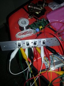
A homemade heatsink for power mosfets.
Luckily, I had several pieces of pre-drilled metal and sol pads already available. After attaching each transistor to the piece of metal and using every available alligator clip at my disposal to connect each transistor to the circuit I built on the breadboard, I tested the circuit again. Again, I was still having problems as the circuit was still drawing a high amount of current (around 4.89A). I later found out that the way I was driving my pchannels was completely wrong. For pchannel mosfets to be fully off, the gate voltage must be equal to the source voltage. Because of my inproper way of controlling the pchannel mosfets, this caused a short in my Hbridge. So now I have to completely revise my previous hbridge control circuit in favor of a new one.
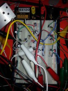
New motor control circuit. Surprisingly used less parts than the last circuit.
After testing the new circuit, I still saw a high current draw (again, around 4.89A). It was later revealed that my arduino was turning on both pchannels of my Hbridge, even though I specify in my code that only one pchannel should be on at a time. In other words, this caused yet another short in my Hbridge.When I looked at the voltage Arduino’s onboard 5v regulator was outputing, I found it that instead of outputting close to 5V, it was outputting 3.5V. Long story short, I need to replace my Arduino.
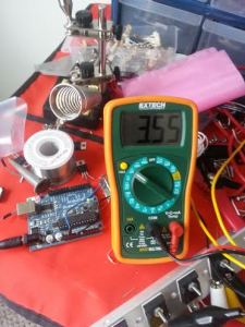
To see if my Hbridge was still working, I provided the input voltages using an 7815 voltage regulator. Now my circuit was drawing the correct amount of current!
Correct current draw. The circuit/motor was drawing 280ma and not 2.80 amps.
Well, that’s it for me today. Not only will I post the parts I used and the theory of the motor controller circuit soon, but I will keep you guys updated on the progress on this project. If you have any questions, comments, or concerns, feel free to leave a comment!
 Well, this is a first. This is kind of an embarassing first, but a first nevertheless. In my two years blogging on Cool Cap Engineer, I could never get past a third update for any of my projects. A lot of the times, I cancelled a project due to the huge time commitment for a project, or the lack of knowledge on the project’s topic. With that said: here’s the 4th update for the 24V Brushed DC Motor Controller Shield project.
 The final thing I was thinking doing for the project was implementing the MC33035 brushless motor controller on the shield. The MC33035 can not only control DC motors, but it comes with a current limit. If I have time this week, I will implement the undervoltage and overvoltage protection circuitry with the 12V Buck regulator circuit and start working on the PCB for the shield, which will control 1 motor. Once I test the shield, I will modify the shield to control 2 motors.


